Original Link: https://www.anandtech.com/show/729
Heatsink Guide - AnandTech's new Testing Methodology
by Tillmann Steinbrecher on March 6, 2001 12:00 PM EST- Posted in
- Guides
Tomorrow we will be publishing our first Socket Cooler Roundup in four months, however this time around the roundup will be quite different from what you may be used to. Along with an updated set of coolers, we will also be introducing the first results based on an entirely new heatsink testing methodology.
In last November's roundup, we measured temperatures using the Abit KT7's onboard thermistor. This test was already showing signs of weakness as four coolers reached the same temperature levels. As more high-performance coolers enter the market it becomes obvious that a new, more accurate testing methodology is required in order to show smaller temperature differences between cooler models with otherwise very similar performance.
Future AnandTech cooler roundups will consist of four tests:
1) A performance test using a "simulator" device: This provides an artificial heat load and allows very accurate measurements. We had used a very similar setup for the Slot-A cooler tests; however the new device is designed for simulating a socketed CPU.
2) A noise measurement test
3) A test under real-world conditions, with an actual Athlon CPU
4) The fan tests, where fan air speed is measured
In this article, we will have a closer look at these tests and provide you
with an outline for what you can expect in our next-generation of cooling reviews.
The Simulator Device
Why use a simulator instead of a real CPU? The simulator solves two problems that are present with CPUs.
First, it is hard to tell how much power a CPU currently produces - the maximum heat emission values specified by the manufacturers are worst-case values, which will not be reached even when running seti@home, prime95, or similar programs. In order to reach the maximum heat emission, CPU manufacturers offer special programs that execute a specific set of instructions to heat the CPU up as much as possible.
In the case of AMD, this program is not available to the public; and according to a heatsink manufacturer, a proprietary PCI card is required to run it. Therefore, we need a simulator device if we want to know how much heat exactly is dissipated by the heatsink.
Secondly, AMD CPUs do not have an internal diode to measure CPU temperature, and in the case of Intel CPUs, the internal diode is not accurate enough for good measurements. So it is not possible to measure the temperature there, where it matters, inside the CPU core. With a simulator, the temperature can be measured right in the simulated die.
This simulator design is not an AnandTech-only project. After the last AnandTech cooler roundup, a small mailinglist was created, where we - Joe Citarella from overclockers.com, Stephen Hoar from burningissues.net, Andrew Lemont from Millenium Thermal, Jim from benchtest.com and John Carcich, discussed various possibilities for testing coolers in a more accurate way.
AnandTech's simulator consits of an aluminum plate milled to the exact shape of an Athlon CPU. On the lower side of the simulator, a foil heater is installed (Minco heater model HK5578R4.6, installed using ArcticSilver epoxy), which provides the heat load. In the center of the simulted "die", a small channel is milled. There, a thermocouple (T-type) is embedded, using ArcticSilver thermal epoxy, too. After installation, the simulated die was lapped.
The CPU simulator is installed in a normal Athlon motherboard (Abit KT7-RAID).
In order to minimize the amount of heat lost through secondary heat paths, the following measures were taken:
- The backside of the heater is covered with a 30x30mm copper sheet, which is glued to the heater and the simulator using ArcticSilver thermal epoxy. This leads the heat emitted on the backside of the heater to the simulator.
- The entire simulator (except for the simulated die, of course) is insulated using self-adhesive Teflon foil (CMC Klebetechnik Order no. 75100, which is temperature resistent to up to 200°C)
- The cavity inside the CPU socket is insulated using Teflon wool
Here are a few pictures of the simulator:
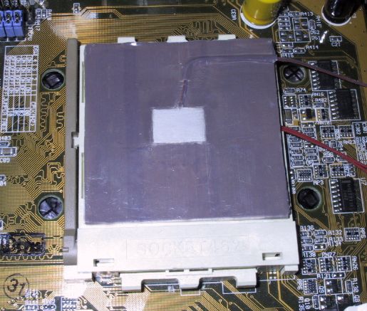
The finalized simulator installed in a motherboard
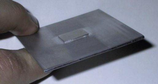
The raw simulator, before sensor and heater were installed
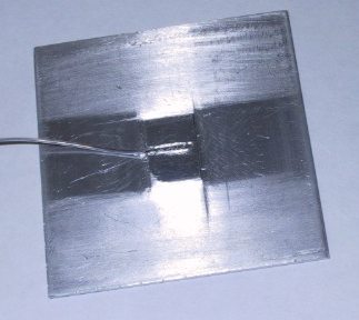
The raw simulator with the sensor, before thermal epoxy was applied
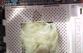
The CPU socket of the test motherboard. Note the groove for the heater's leads,
and the teflon wool inside the socket.
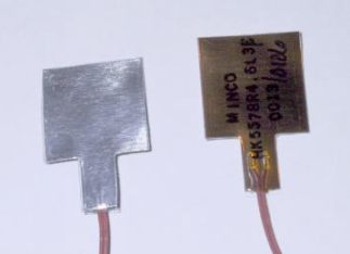
The foil heater used for the simulator (view from front and back)
We chose this heater because, with its size of 19.5x19.5mm, it fits perfectly in the center part of the CPU socket. Its resistance of 4.6 Ohms makes it suitable for simulating common heat loads with a standard 0-25V power supply. Unfortunately, the wattage of this heater is limited; we killed one heater trying to push it to a heat load of 80W. Therefore, in our current setup, we use a heat load of 43W.
The resistance of the heater has a very high tolerance (10%); therefore, a power supply with adjustable voltage is required. Our heater would run at 43W with 14.19V / 3.03A. In future simulator setups, we will be using higher heat loads. For this, a heater with similar mechanical characteristics than the Minco heater, but suitable for higher wattages, would be required. So far we have found none and we would appreciate reader feedback on this point.
For persons with serious interest in how to build their own simulator using our plans - please email tillmann.steinbrecher@anandtech.com and we will send you drawings by email.
A frequently asked question is: Why don't we use the heatsink testing methodology suggested by AMD?
AMD recommends to test heatsinks by drilling a hole into the heatsink, and embedding a thermocouple there. The problem with this method is that it only measures the heatsink performance, but not the performance of the entire cooling system. Not only does the heatsink's performance itself determine the cooling performance under real-world conditions, but the quality of the heatsink contact area (the flatter, the better) and the clip (the more pressure, the better) can have a major effect on cooling performance. For this reason, we chose to use a test setup where the quality of the heat exchange between CPU and cooler is taken into account. This means that if you calculate the cooler C/W based on our test results, you will always get higher values than those obtained using the AMD-recommended method, since our values include the interface.
One thing our simulator setup does not take into account is the cooling of
the CPU through the motherboard. In the case of a real CPU, a part of the heat
travels through the CPU's pins to the motherboard's leads, where it is dissipated
- in other words, the motherboard itself also acts as a heatsink. With our simulator,
there is no considerable heat path between the heat source and the motherboard's
leads and this effect is not considered. Therefore, coolers which only provide
poor air flow to the motherboard (in particular the Alpha models and the Kanie
Hedgehog, which suck air away from the cooler) will perform better in our simulator
test than in the test with a real CPU.
Noise measurements
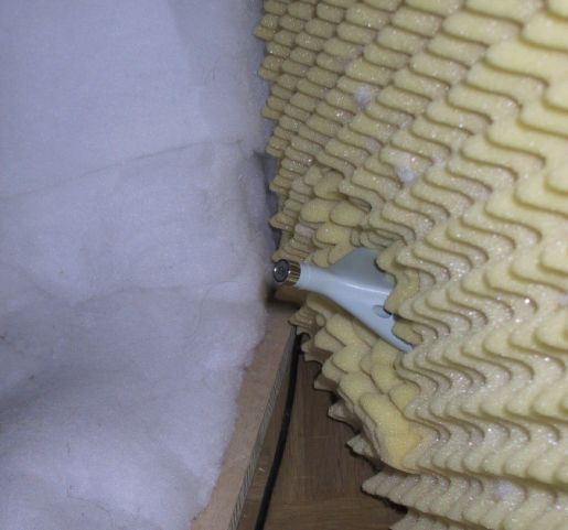
For our noise measurements, we chose to use the same testing methodology as Tom's Hardware Guide. This way our results can directly be compared to the results published there - which is convenient, since we do not always test all the models reviewed there and vice versa. The test setup consists of a soundproof box in which the fan noise is measured using a Lutron SL-4001 sound level meter.
We were not able to reproduce the results from Tom's Hardware Guide exactly, but we got very close. The differences can be explained by tolerances of the fans (rpm varies) and the slightly different design of the sound proof box.
Here is a photo of our sound-insulating box. The gray thing you see on the right is the head of the sound level meter.
What about the remaining tests?
The test under real-world conditions and the fan air speed tests have already
been described in the November
2000 cooler roundup.
The Test Equipment
Here is a picture of the test setup:
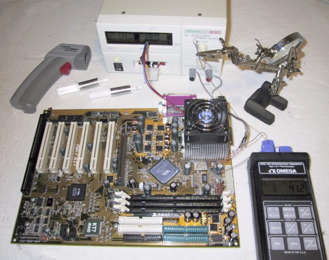
The following equipment was used for testing:
Thermometer: Omega
HH23
Thermocouple: Omega T-type (copper/constantan) thermocouple wire model TT-T-30-SLE
Thermal compound: ArcticSilver II
The gun-like object in the upper left of the picture is a RayTekMiniTemp MT4 noncontact infrared thermometer. We did not use it during the actual testing, but it proved to be highly useful during the development of the test setup, since it instantly provides surface temperatures without having to install a thermal sensor.
The metal stand in the upper right holds the thermal sensor that measures ambient temperature. The temperature readings to be published in the cooler roundup are the temperature differences between simulator temperature and ambient temperature. This way, small changes of the ambient temperature will not influence test results in a significant way. The ambient temperature sensor is located above the fan; in the case of the Kanie Hedgehog and the Alpha PAL35, where the fan sucks air away from the cooler, the temperature sensor was relocated to the side of the cooler (15cm away from the heatsink).
Ambient temperature is 19.5°C +- 0.2°C.
Based on our experience in numerous tests, reproducibility of the test results was +- 0.2°C. We test each heatsink three times and publish the average of the three tests.
Final Thanks
We would like to thank those in the community that helped us develop this new testing methodology as well as the members of the AnandTech Forums that pointed out the flaws with our previous system and helped push us to develop this new methodology. Thanks guys.


